VisualHDL - Best Practices
This page presents efficient development techniques when using VisualHDL with THDL++.
-
Use multiple build configurations. E.g. your are
developing a microcontroller consisting of a processor and an LCD
controller. The microcontroller will run on the FPGA. You can simplify
testing by making separate testbenches for each of the components. You
will need the following build configurations:
Using 5 configurations instead of just one allows quickly retesting changed functionality. For example, if the LCD controller implementation has been changed to support different display resolution, you can make a small modification to the LCD testbench and look at the signals in the simulator without recompiling the processor and changing the firmware. You can then quickly test the new controller on the FPGA without resynthesizing the complex processor code.Configuration Type Description LCD Test Simulator A stand-alone simulator testbench for the LCD controller. Writes some fixed text to the buffer. Convenient for checking LCD updating state machine. To simplify simulator view, all pules lengths can be reduced to 1 clock cycle. Hardware LCD Test Hardware An FPGA-based equivalent of the previous test. Uses real pulse lengths. Allows checking the design with a real LCD connected to the FPGA. Processor test Simulator A stand-alone CPU test that runs a hardcoded program. Useful for debugging the processor. Hardware processor test Hardware Similar to the previous test. Allows checking real-time performance on a real FPGA. Final setup Hardware Contains both processor and LCD controller. Processor runs from an external FLASH memory. Used as a "release build". Each configuration will have its own root entity. Additionally, some small differences (e.g. pulse length) may be needed. To get it working, let's first have a look how VisualHDL determines the root entity.
When you build a THDL++ project, VisualHDL searches all source files for the root directive. For simulator-based configurations it looks the following way:
simulate_entity(SimulatedClockProvider<20ns, LCDTestbench>);The root entity should be a testbench that generates its own clock. In most of the cases you can reuse the templated Core.Primitives.SimulatedClockProvider entity. The first template argument specifies the clock period. The second specifies your entity that you want to be clocked. Note that your entity needs to have an input called "clk" for the SimulatedClockProvider to handle it correctly.
For hardware configurations the root statement looks differently:
synthesize_hardware<"xc3s700an-fgg484-4"> LCDTestbench(
clk="E12",
LEDs="W21,Y22,V20,V19,U19,U20,T19, R20");The synthesize_hardware statement specifies the root entity, the FPGA device type and maps the ports to the FPGA pins. When using Xilinx toolchain, VisualHDL will generate all required files (e.g. UCF) automatically and will produce a ready-to-program BIT file. Note that you can program the BIT files directly from VisualHDL by selecting "Project->Run" when an FPGA configuration is active.
For post-route simulation you will need an extended form of synthesize_hardware:
synthesize_hardware<"xc3s700an-fgg484-4"> LCDTestbench(
clk="E12",
LEDs="W21,Y22,V20,V19,U19,U20,T19, R20"
) post_route_sim(SimulatedClockProvider<20ns, LCDTestbench>);This tells VisualHDL to build an FPGA bitstream using LCDTestbench as the root entity and use SimulatedClockProvider to generate its inputs.
If VisualHDL discovers several root directives of the same type (e.g. simulate_entity), it shows an error and stops compilation. To support several configurations simply place #ifdef statements around the root directives:
#ifdef LCD_TESTBENCH
simulate_entity(SimulatedClockProvider<20ns, LCDTestbench>);
#endif
#ifdef CPU_TESTBENCH
simulate_entity(SimulatedClockProvider<20ns, CPUTestbench>);
#endifFinally, go to configuration editor (the "..." button in the project explorer) and make two simulator configurations:
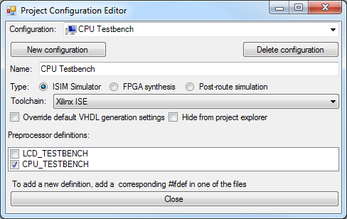
Enable one of the XXX_TESTBENCH definitions in each of the configuration. Now you can easily switch between the configurations in the Project Explorer without changing any code. Moreover, VisualHDL will maintain separate build directories for the configurations and even separate ISim wave configuration files, so that you can rebuild and run both testbenches fully independently!
Note that the simulator configurations will have the __SIMULATOR__ definition enabled (and either __BEHAVIORAL_SIMULATOR__ or __TIME_ACCURATE_SIMULATOR__ as well).
-
Use source folders. If you want to group several source files together, use the "Create Virtual Folder" command in Project Explorer context menu. Then, drag the input files into the newly created folder. Virtual Folders won't move the files on the disk, they will only regroup the files in the IDE.
-
Use libraries. Instead of copying reusable THDL++ files, place them in a library ("New shared THDL++ library" command). Reference the library from every project where you need to reuse the code.
-
Use version control. VisualHDL file layout is SVN-friendly. All temporary build files are placed into "Configuration_name.hdlbin" directories, so all you need is to add *.hdlbin to the global ignore list. ISim configuration files are stored inside BackendFiles directory.
-
Use keyboard shortcuts. Press Ctrl+F7 to recomplle THDL++ into VHDL. Press F7 to build the entire design (generate simulator executable or the bitstream file). Press F5 to run the simulator or program the FPGA (use Shift+"run" button instead to bypass automatic rebuilding). Press F8 to jump to the next error. Press Ctrl+Tab to navigate between the source files in the least-recently-used order. Press F12 to open entity/signal/function/etc declaration.
-
Use design visualizer to explore designs. Press F6 to open it. Double-click at entities to go inside them. Ctrl+Click at anything to navigate to the declaration.
-
Edit the XML files inside ProjectBuilders\ToolConfigs to customize the command line templates of Xilinx tools. Look for *.cmd_log files inside your ISE project directory to import the command lines the ISE Project Navigator uses.
-
Use regions to improve code readability. A region is declared using the #region directive and can be collapsed by clicking at the corresponding "-" sign to the left of the code:
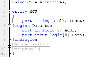
A good practice is to declare regions inside a long entity/process/method so that collapsing them all makes it fit in one screen and helps seeing the "big picture" not caring about the exact implementation details.